Dave Vollmer's


 N Scale Juniata Division


  Modeling the "Standard Railroad of the World" in two eras

TRAINPHONE

April 2007: Installing PRR Trainphone antennae on the N scale Juniata Division!


Page updated 8 Nov 2008.


Note:  All photos, videos, and images (except for the Pennsylvania Railroad logo) contained herein are Copyright 2006-2008 Dave Vollmer and may not be used without permission.

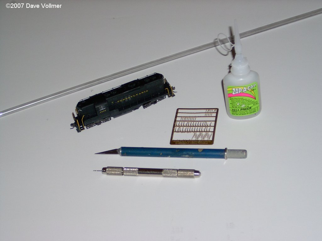
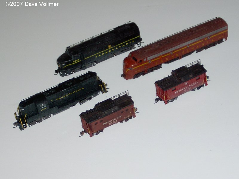
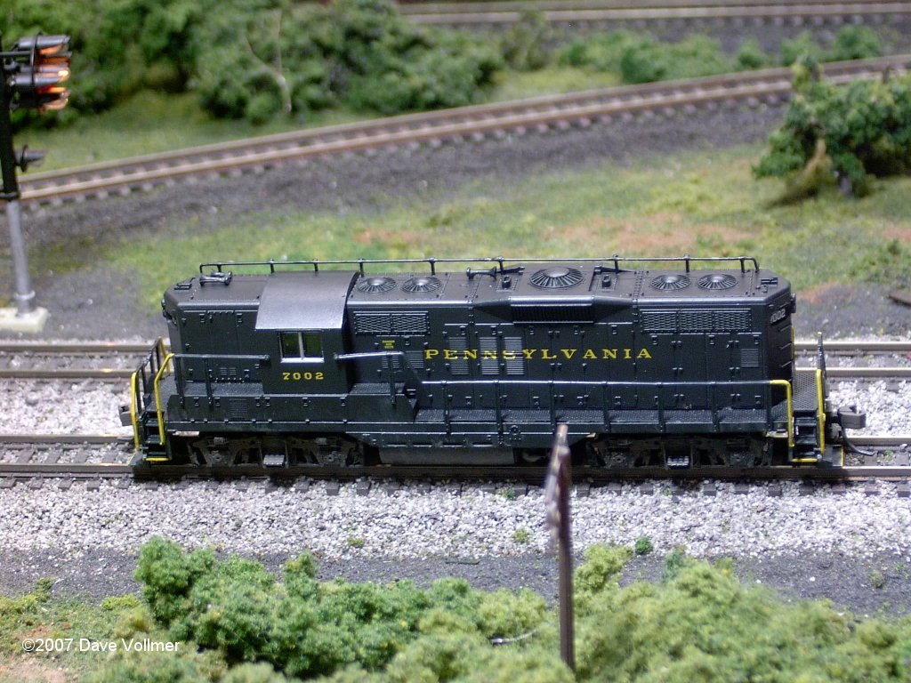
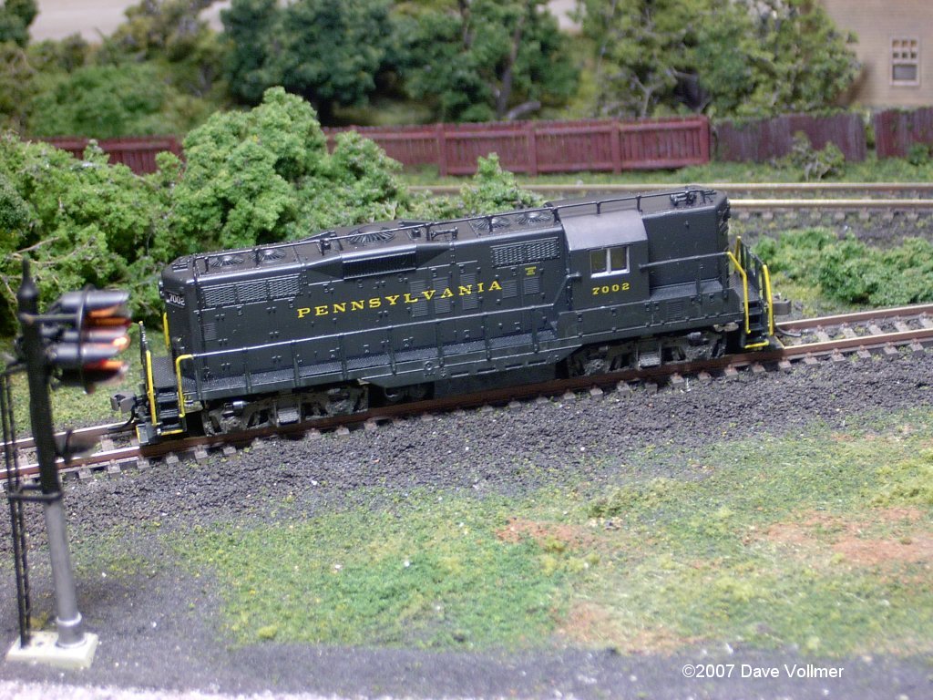
People modeling the PRR of the 1940s and '50s often attach strange-looking handrail-like devices on top of their locomotives and cabin cars. These are the PRR's unique Trainphone antenna arrays.

What is "Trainphone," anyway? Let's ask Wikipedia!

Trainphone was the Pennsylvania Railroad's system for voice communication between train crews on moving trains and with dispatchers, tower operators and similar. It did not use radio, but rather electromagnetic induction. Railroads did not own any radio frequencies at the time, and the PRR's busy network found the previous methods (passing a physical paper message, or requiring a train to stop to pick up orders) insufficient. The trainphone system was first trialled in 1936 and perfected by 1943. The system used the track itself, or lineside telegraph wires, as the "shore" transmitter. The trainphone signal — low frequency current in the hundreds of kilohertz — was passed through the track or wires and induced a corresponding current in the locomotive or car's receiving antenna. The range was only a hundred feet or so, but this was sufficient.

Mobile trainphone antennas took the form of long, handrail-looking structures atop the tender of steam locomotives, atop the bodies of diesel locomotives, or running the entire length of a cabin car (PRR-ese for caboose). The engineer or other crew member would talk through a regular-looking telephone handset. An attention loudspeaker was also installed, but it was easier to hear the messages with the handset.

The biggest problem with the trainphone system was that it could not work in electrified zones, because of interference from the electric supply and electrical equipment on the locomotive. Since the electrified zones were among the PRR's busiest, this was a serious disadvantage. The trainphone system was abandoned in the 1960s as radio took over.

References
Britton, Jerry et al.. What Was the Pennsy's "Trainphone" System and How Did It Work?. Keystone Crossings. Retrieved on 2005-01-17.
Daniels, Rudolph (2000). Trains Across the Continent: North American Railroad History (Second Edition). Indiana University Press, 195. ISBN 0-253-21411-4.
Retrieved from "http://en.wikipedia.org/wiki/Trainphone"

So, in order to better represent unique PRR radio equipment, we'll need to modify our as-built N scale trains.

Fortunately, Gold Medal Models makes etched brass stanchions (supports) for Trainphone antennae in N. Included are induction coils for cabin cars and 4 different types of stanchion. Let's add a Trainphone antenna to Atlas' new GP9.

This is the stock Atlas loco from their website. Great detail. No Trainphone.
We'll need: 1 GP9, .015" piano wire, Gold Medal Models' Trainphone supports (part number 160/33), a pin vise, a hobby knife, and gap-filling CA glue.

Now, the directions with the antenna supports call for very thin wire. I use .015" piano wire. It's much heavier than what the directions call for, but I travel a lot with my models, so I handle them frequently. As such, I use a thicker, sturdier wire. I think once the wire's painted, you can't really tell the difference. Use photographs to place the holes you'll drill with your pin vice. I have several of the Pennsy Diesel Years books, and in them are plenty of views of GP7/9 roofs to use as a guide. In our case we need 10 holes (9 for supports and 1 where the wire enters the hood). I use tape to make a straight edge to guide the holes as I drill so they stay in a perfect line. I suggest removing the shell before drilling so you don't drill into the electronics below!

I make the first bend in the wire where it enters the short hood. Then, I put that end in the first hole and then measure out to where the other bend goes. In our case, the wire continues down the fireman's side of the long hood (remember, on Penny the long hood goes forward!). I then attach the first, last, and middle supports using thick, gap-filling CA glue. Some folks like to solder... and I hope they have fun doing it. For me, the gap-filling CA is easier to control and avoids overheating the plastic below. I'm not the most skillful with a soldering iron, that's for sure! Once I have the antenna the way I want it, I finish attaching the rest of the supports. Start by dipping the bottom of each support in a dap of thick CA, and place it in the hole. Lean it against the antenna wire, and then dab a tiny bit of the CA over the gap. Let dry. Repeat until done!

It's tough to match the paint of a factory-decorated model. No worries, however. Roofs always weather quickly (especially on diesels). Even engines fresh through the wash-racks usually have dirty roofs. So, close is good enough.

Here are some samples of I've done. They include an E-R Models Sharknose, a Kato E8A, two Bowser cabin cars (an N5 and an N5C), and our Atlas GP9.
So, how does the GP9 look now that I'm done? More Pennsy-fied, that's for sure. Also, I painted the handrails yellow following PRR practice.
A little light weathering on the fuel tank and trucks, and she looks like she's made a few runs over the Middle Division. Now she needs a mate!

Copyright 2006-2008 Dave Vollmer.